Radio Communication Using NRF24L01 Module and Demonstrating it by Making Joystick and a Wireless Car - Group 6
This blog is written by
- S.Mohith Saikiran
- A.D.N.Venkatesh
- B.Manohar Naidu
- T.Charan Reddy
Motivation:
If you're searching the internet to buy a good wireless remote controller for your car or if you want to use it for some project, you'll find it very expensive.So we thought we'd do it ourselves and our main goal is to make it cheaper and more efficient.There is not much difference between the controller we are making in this project and the controllers used for drones etc..they may be treated as an extension of our controller.Every thing runs on same basics of communication.And if you are looking for some good communication projects,You will also find that making a good controllable car is a good starting point for wireless communication projects because they have applications in many other projects.
Introduction:
This blog explains the process of making a robocar and a remote controller for this car from scratch.We also explained the uses and functionalities of each and every component,the process of interfacing them and the protocols used to establish communication in detail.
These are the list of the components that we used.
1. Arduino uno - 2
2. Car chassis -1
3. Dual shaft gear motors -2
4. L298N Motor driver
5. 9-Volt batteries-2
6. 1.5-Volt batteries-5
7. 5-Battery holder
8. NRF24L01 Module -2
9. 3.3 volt regulators for NRF24L01 Module -2
10. Joysticks -1
11. Pcb board
12. Soldering kit -1
We've seen the components so far now we will explain them in detail.
Description of components:
Arduino uno:
- Arduino uno is the microcontroller we use in our project.
- It acts as an interface between our receiver part and the sending part.
Motordriver:
Figure-2.

- The L298N module is a dual H-bridge motor driver which allows speed and direction control of two dc motors at the same time.refer to figure 2.
- This module can drive the dc motor voltages between 5 volts and 35 volts.
- The motor driver has a on board 5volt voltage regulator which can be enabled or disabled by using a jumper.
- If the motor supply voltage is below 12 volt, then enable the regulator. If it is greater than 12V then disable the regulator as it may damage the board.
- There are logic inputs on this module which are used to control the speed of the motors the use the process of pulse width modulation for speed control.
- From the picture below inputs 1 and 2 are used to control the rotation motor A and inputs 3 and 4 are used for motor B.
- Figure-3.
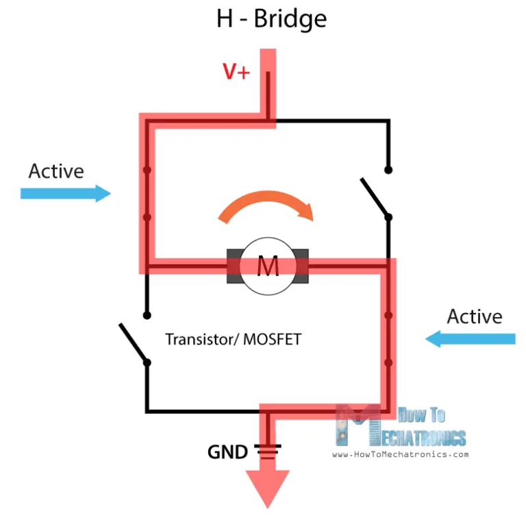
- Using these pins we actually control the switches of H- bridge which is the main reason for direction of rotation.Refer to figure 3 for better understanding.
INPUT 1 INPUT 2 MOTOR MOVEMENT
Low High Moves forward.
High Low Moves backward.
Low Low Motor stops.
High High Motor stops.
The same table for inputs 3 and 4.
Note:
The motor driver module we are using has a H-bridge control for controlling the direction of motor rotations,for doing this we just need to inverse the direction of current flow through the motor and the most common method for doing this is H-bridge.
For more details about motor driver and h-bridge visit this site
Motors:

- We have used two geared motors which are connected to the wheels for our robocar and a rear caster to balance the two wheels.refer to figure 4.
- These motors provide a greater torque than normal motors and can be used in carrying some load as well.
- Figure-4
- S.Mohith Saikiran
- A.D.N.Venkatesh
- B.Manohar Naidu
- T.Charan Reddy
Motivation:
If you're searching the internet to buy a good wireless remote controller for your car or if you want to use it for some project, you'll find it very expensive.So we thought we'd do it ourselves and our main goal is to make it cheaper and more efficient.There is not much difference between the controller we are making in this project and the controllers used for drones etc..they may be treated as an extension of our controller.Every thing runs on same basics of communication.And if you are looking for some good communication projects,You will also find that making a good controllable car is a good starting point for wireless communication projects because they have applications in many other projects.
Introduction:
This blog explains the process of making a robocar and a remote controller for this car from scratch.We also explained the uses and functionalities of each and every component,the process of interfacing them and the protocols used to establish communication in detail.
These are the list of the components that we used.
1. Arduino uno - 2
2. Car chassis -1
3. Dual shaft gear motors -2
4. L298N Motor driver
5. 9-Volt batteries-2
6. 1.5-Volt batteries-5
7. 5-Battery holder
8. NRF24L01 Module -2
9. 3.3 volt regulators for NRF24L01 Module -2
10. Joysticks -1
11. Pcb board
12. Soldering kit -1
We've seen the components so far now we will explain them in detail.
We've seen the components so far now we will explain them in detail.
Description of components:
Arduino uno:
- Arduino uno is the microcontroller we use in our project.
- It acts as an interface between our receiver part and the sending part.
Motordriver:
Figure-2.
- The L298N module is a dual H-bridge motor driver which allows speed and direction control of two dc motors at the same time.refer to figure 2.
- This module can drive the dc motor voltages between 5 volts and 35 volts.
- The motor driver has a on board 5volt voltage regulator which can be enabled or disabled by using a jumper.
- If the motor supply voltage is below 12 volt, then enable the regulator. If it is greater than 12V then disable the regulator as it may damage the board.
- There are logic inputs on this module which are used to control the speed of the motors the use the process of pulse width modulation for speed control.
- From the picture below inputs 1 and 2 are used to control the rotation motor A and inputs 3 and 4 are used for motor B.
- Figure-3.
- Using these pins we actually control the switches of H- bridge which is the main reason for direction of rotation.Refer to figure 3 for better understanding.
Low High Moves forward.
High Low Moves backward.
Low Low Motor stops.
High High Motor stops.
The same table for inputs 3 and 4.
For more details about motor driver and h-bridge visit this site
Motors:
- We have used two geared motors which are connected to the wheels for our robocar and a rear caster to balance the two wheels.refer to figure 4.
- These motors provide a greater torque than normal motors and can be used in carrying some load as well.
- Figure-4
Joystick module:
This is a dual axis xy joystick module for arduino. refer to figure5.It is a analog module.
It gives different analog values as output based on the angle we tilted and direction we moved.

Figure-5.
NRF2401 module:
- This is a trans receiver module.
Figure-6
Shock buster protocol:
Shock buster protocol:
- This module uses enhanced shock burst protocol in order to support two way data packet communication with packet buffering,packet acknowledgement and automatic retransmission of lost packets.Refer to figure 6 for better understanding.
- Figure-7.
- 3.3 volt Regulator:
- NRF24L01 module works at 3.3 volt.So better use a 3.3 volt regulator so that we can exactly get 3.3 volts supply.Refer to figure 7

1.Module with integrated antenna.
Figure-8.

Figure-8.
2.Module with external antenna.
figure-9.

figure-9.
Difference between module with integrated and module with external antenna:
The module with an external antenna comprises of a LNA(low noise amplifier).This helps us to get rid of noise.This module is also used for larger distance communication upto 1100 meters.
Where as the integrated antenna can only be used for 100 to 200 meter communication.
For more details about this module go to this site
Till now we discussed about the details of all the modules used,now we describe the process of building the robocar from scratch.
Process of building a robocar:
We will discuss the making by dividing the process in to two parts first part is describes about the cars side circuit construction and the second part describes about the controller side circuit construction.Car making:
Circuit diagram of the receiver side:
Figure-10.
Figure-10.

Explanation:
figure-11. Base of chassis

figure-11. Base of chassis
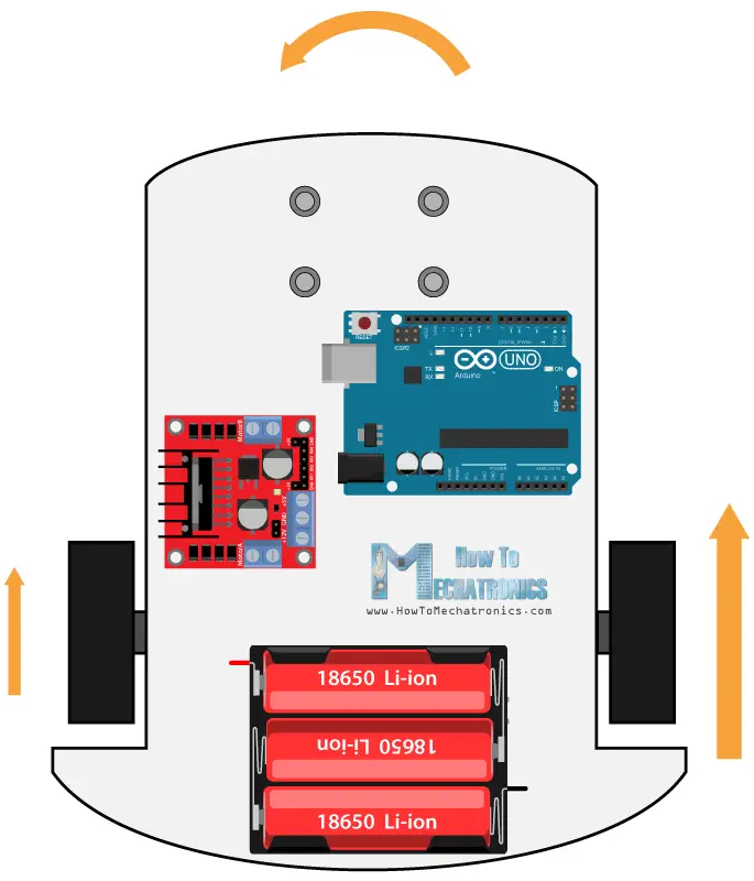
- Firstly the chassis, it has a base and this base is drilled with a number of holes which are used to fix some modules and parts with the help of screws through these holes.
- Arrange the parts on the base symmetrically so that center of mass of car is approximately at its center,which provides stability to car.
- Fix the motors,wheels and arduino on the base.A nine volt battery is used to power arduino.
- Then fix the motordriver module and a battery holder which is used to give input to motordriver.
- figure-12.
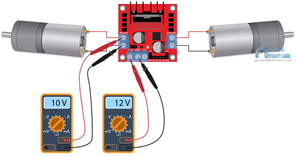
- A 5 battery holder is better than a 4 battery holder because the motor driver drops 2 volt which reduces the output voltage supply which is used as input to motors and effects the velocity of car.See the figure-12 for better understanding.
- Connect the above output to motor A and B.
- Figure-13.

- Then connect the output logic control pins from arduino to input pins between the enable pins(PWM pins).refer to figure-13 for better understanding.
- The pin numbers should be connected as defined in code.
- Check weather the control information is going to arduino to motors or not by using a test code.
- Then connect a NRF24L01 module to a 3.3 voltage regulator and connect it to arduino,then fix it to base.
- Connect the ground and vcc to all modules.
- Now the receiver part is ready to receive the information.
Circuit diagram of controller:

Figure-14.

Figure-14.
Explanation:
- Use the other arduino connect the joystick module to it.
- Then connect the NRF24L01 module to its regulator.
- Then connect the module to arduino.
- Connect all the primary connections like ground,vcc.
- The controller is ready.
Then use the test codes to check whether the communication is established or not.
Note:
1. When you are working with arduino about these modules we should download some libraries which has in built functions.Using these functions will make our work easier.
List of the libraries used:
- RHReliableDatagram.h
- RH_NRF24.h
- SPI.h
2. These are obtained by downloading radiohead library.
Go to tools in Arduino IDE and select the manage libraries in the drop down.Now search the radiohead library and install it.
Figure-15.
Bread board:
Figure-15.
Bread board:

- Use a breadboard because we need to give same connections to multiple modules.
- At last use pcb and solder all the wires on it permanently,this gives a good finish because it covers all the hardware components and the device will be strong to withstand loose connections.
Finally the robocar is ready to use.
- Use a breadboard because we need to give same connections to multiple modules.
- At last use pcb and solder all the wires on it permanently,this gives a good finish because it covers all the hardware components and the device will be strong to withstand loose connections.
Conclusion:
The codes are not included in this blog.We demonstrated the connections and uses of all the modules clearly.Its easy to write a code once we know the process.
We hope our blog makes your work simpler.
We hope our blog makes your work simpler.
Client server communication and protocols used:
- The cars NRF24l01 module can be treated as a server as it is always open and waiting for requests.
- Our other NRF24L01 module on the other acts as a client and exchanges control information before sending joystick data to server and establishes a connection.
- We can also use a normal client server communication,but we used reliable datagram client server protocol.
- If we use normal client server communication,it can only be used to exchange messages with out reliability.If a packet is lost due to some reason then it is not going to re-transmit .
- But since we make use of this communication to an application in real time,we cannot really afford to lose packets.
- So we used Reliable User Datagram communication Protocol,which is similar to TCP (Transmission control protocol) that guarantees packet delivery.
Then you may have a doubt.Why not to use the TCP protocol itself?
- TCP protocol avoids the loss of packets by decreasing the throttle of the information sent so that it helps to get rid of congestion.
- But several real time applications like video streaming,gaming and even in our project case we cannot decrease the throttle since speed of transmission is important.
- So the UDP protocol which offers a connection less service for greater data transmission rates.So this is too not favorable for our case.It is equally important not to loose the packets in the way.
So we use RUDP.In computer networking RUDP protocol is a transport layer protocol designed for providing the solution where we cannot use UDP since it is not reliable and TCP since it cuts throttle in some cases and due to its complexity.
RUDP implements features that are similar to TCP with less overhead and thus gains high quality of service(QOS).
It carries out the following implementations:
1.Acknowledgement of received packets.
2.Windowing and flow control.
3.Re-transmission of lost packets.
4.Over buffering(Faster than real time streaming).
- By this over buffering it can extend the buffer to a large extent.
- This gives the time to avoid congestion and send the packets already that are ought to be sent in the waiting list.
Hence we are using this Reliable User Datagram Protocol and this also add encryption and other security features to it.
- The cars NRF24l01 module can be treated as a server as it is always open and waiting for requests.
- Our other NRF24L01 module on the other acts as a client and exchanges control information before sending joystick data to server and establishes a connection.
- We can also use a normal client server communication,but we used reliable datagram client server protocol.
- If we use normal client server communication,it can only be used to exchange messages with out reliability.If a packet is lost due to some reason then it is not going to re-transmit .
- But since we make use of this communication to an application in real time,we cannot really afford to lose packets.
- So we used Reliable User Datagram communication Protocol,which is similar to TCP (Transmission control protocol) that guarantees packet delivery.
- TCP protocol avoids the loss of packets by decreasing the throttle of the information sent so that it helps to get rid of congestion.
- But several real time applications like video streaming,gaming and even in our project case we cannot decrease the throttle since speed of transmission is important.
- So the UDP protocol which offers a connection less service for greater data transmission rates.So this is too not favorable for our case.It is equally important not to loose the packets in the way.
RUDP implements features that are similar to TCP with less overhead and thus gains high quality of service(QOS).
It carries out the following implementations:
1.Acknowledgement of received packets.
2.Windowing and flow control.
3.Re-transmission of lost packets.
4.Over buffering(Faster than real time streaming).
- By this over buffering it can extend the buffer to a large extent.
- This gives the time to avoid congestion and send the packets already that are ought to be sent in the waiting list.
Future Applications of robocar:
- We can add a lot of applications for our robotcar,we can add an ultrasonic sensor for obstacle detection,we can set up a webcam and perform image processing for object detection,it can also be a fire fighting robot if we add some features to it.
- We can use the controller in this project for many other purposes for example for controlling drones,rc plane etc.
- This project is actually a start to our next project i.e making a drone from scratch which has many similar things with this project i.e about stability,speedcontrol,joystick etc.
- Our project is the basis for many other applications so it is the best step to get started.
References:
Image references :
1. Image of motor driver link
2. Car chassis image link
3. Motor driver picture 2 link
4. Integrated antenna module picture link
5. External antenna module picture link
6. Gear motor image link
7. H-bridge picture link
8. NRF24L01 module regulator picture link
9. Shock buster protocol picture link
10.Figure-10 is a screen shot from youtube video link
All the other pictures i used are not cited because they are screenshots from a opensource arduino circuit simulating software named fritzing and edited in powerpoint.
Other references -
1.https://dronebotworkshop.com/nrf24l01-wireless-joystick/
2.https://howtomechatronics.com/tutorials/arduino/arduino-dc-motor-control-tutorial-l298n-pwm-h-bridge/
3.https://lastminuteengineers.com/nrf24l01-arduino-wireless-communication/
We thank you for reading our blog.
1. Image of motor driver link
2. Car chassis image link
3. Motor driver picture 2 link
4. Integrated antenna module picture link
5. External antenna module picture link
6. Gear motor image link
7. H-bridge picture link
8. NRF24L01 module regulator picture link
9. Shock buster protocol picture link
10.Figure-10 is a screen shot from youtube video link
All the other pictures i used are not cited because they are screenshots from a opensource arduino circuit simulating software named fritzing and edited in powerpoint.
Other references -
1.https://dronebotworkshop.com/nrf24l01-wireless-joystick/
3.https://lastminuteengineers.com/nrf24l01-arduino-wireless-communication/
We thank you for reading our blog.


Comments
Post a Comment