GROUP 12 : PC to PC file transfer using LiFi Technology
This is an article written by,
Bala Krishna Nair(S20180020201),
J Krishna Chaitanya(S20180020214),
K Samruth Kumar Reddy(S20180020217),
U Yugander(S20180020256) under FCOMM project.
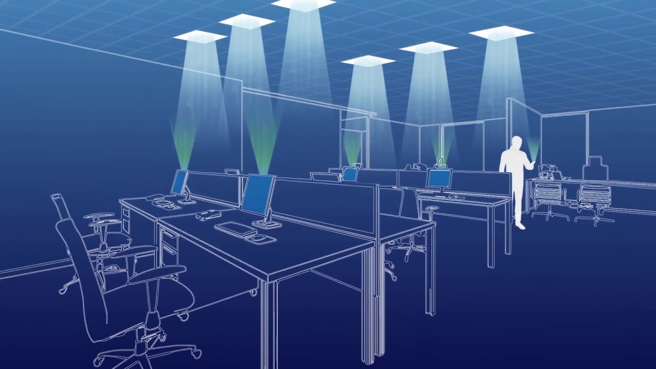
Just imagine a situation where you are obsessed with your work in your PC in a work space with all
the lights on and there is a light just above all the desks, as there is only a single WiFi router in
the work space and as everyone in the work space are working, you and some others also facing
the problem of poor signal, after struggling for sometime you feel like having a separate router only
for you and that too right above your working desk, but you know that it is not possible, now I ask you
how is the data coming from the WiFi router wireless to your PC? Basically WiFi uses waves in the
radio frequency band of the electromagnetic spectrum between actual radio waves and microwaves.

These electromagnetic waves carry the data, WiFi router is like an antenna that emits these invisible
waves, and we know that even visible light is a part of electromagnetic spectrum and what if you can
use the light source just above your desk as a router that emits visible light that carries the data just
like WiFi signals. Now, your normal LED light works in two ways, as a router and as a source of light,
this is like killing two birds with one shot, amazing right!
Taken from : link(youtube)
Why LiFi over WiFi ?
Taken from : link
- This is the future technology the world is waiting to witness, and why this is amazing because as visible light has wider bandwidth(430 - 770TeraHertz), you can enjoy the service of the internet with high data rates i.e up to 100 times faster that WiFi.
- Also it is more secure than WiFi as the radio waves of WiFi can penetrate through walls and there is a chance that someone in the other room or outside can catch these signals and your sensitive data, but this is not the case for visible light because it cannot penetrate through walls.
- LiFi is much safer than WiFi when it comes to health as it only involves visible light for communication.
- Power consumption in LiFi is also less compared to radio wave communication which is the case in WiFi.
In 2011, in a TED talk, a professor named Harald Haas, introduced and coined the name
LiFi(Light Fidelity) to this wonderful technology, it is expected that this tech will be in the market by
the year 2022. LiFi involves full duplex communication mode and as the data is transmitted using
visible light, modulation techniques like On-Off keying(OOK), Pulse Position Modulation(PPM),
Pulse Amplitude Modulation(PAM) can be used but these modulation schemes introduce
Inter Symbol Interference(ISI) in the communication channel, due to these limitations Optical
Orthogonal Frequency Division Multiplexing(OOFDM) is considered in LiFi systems.
However, we have used OOK modulation technique for data modulation at the transmitter in the
project.
project.
Implementation :

Taken from : link
In this blog, a prototype design for short range visible light communication using white LED transmitter
where a file(text, image, audio etc) from one PC is transmitted to another is demonstrated. As
mentioned earlier, as the modulation technique is OOK, and data is transferred wireless in the
form of binary(1s and 0s), if the LED is on, it indicates ‘1’ and ‘0’ when it is off. The LED bulb must flicker rapidly so that it is imperceptible to the human eye but perceptible to the receiver. This is the reason why LED bulbs are used as the transmitter as it can flicker at very high rates(up to 1MHz) but equally sensitive receivers should be used.
Components used in this project are :
- Two Raspberry Pis(as 2 PCs)
- Transmitter side : LED bulb, bread board, few jumpers and resistors(refer figure 2below)
- Transmitter side : LED bulb, bread board, few jumpers and resistors(refer figure 4below)
Transmitter :
- In this project two Raspberry Pis are used as PCs where the transmitter LED is connected to one Rpi and the receiver is connected to another Rpi as shown in fig 1.
- On the transmitter side, first a file is selected from the PC(refer fig1), except the text file all the other files like image, audio etc are first encoded to Base64 format(for details on Base64 click here), this can be done using built in python libraries. In case of a text file, it can be converted to a binary text file directly using python code.
- Now this encoded base64 data is further converted into a binary text file.
- Based on this binary file a python code runs that flickers the LED light bulb and initiates the data transmission(refer fig3-code).

Fig1. Block diagram
- Before the transmitter starts, the receiver should be kept on, after the data transmission completes the transmitter stops automatically.
- But how will the receiver know when to stop reading the data? For this reason we append a redundant symbol “$” at the beginning and end of the binary file, the receiver continues to read the data until it encounters 200 zeros continuously.
- As the actual data exists between the ‘$’ symbols, it can be easily extracted on the receiver side.
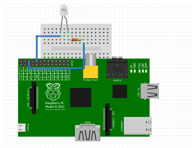
Fig2 : Circuit diagram for transmitter
Code for flickering LED bulb :
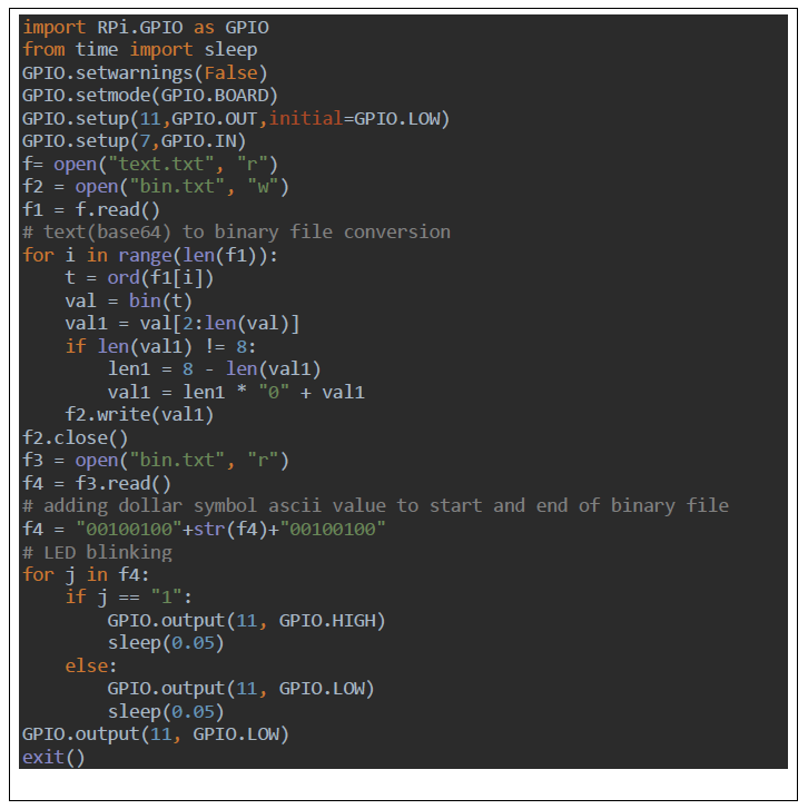
Fig 3. Transmitter code
Receiver :
- On the receiver side as mentioned earlier, an LDR(Light Dependent Resistor or photoresistor) is used to detect the light from the transmitter.
- The resistance of the LDR changes based on the intensity of incident light, more is the intensity of the light lesser is the resistance and vice versa.
- And basically OpAmp is an electronic device that gives output as high(1) or low(0) based on the voltage difference between its two terminals(inverting-pin2 and non inverting terminals-pin3 in the IC LM358).
- The output of LDR is analog value, so by interfacing LDR with OpAmp we get digital output, now lets see how exactly this is happening,

Fig4 : Circuit diagram for receiver
- So in order to use LM358 OpAmp and an LDR to detect light, first provide power supply to the OpAmp by connecting V+(pin8) of IC to 5V supply of Rpi at receiver, and providing ground to pin4 of IC(as shown in fig 4).
- The inverting input(pin2) is hooked to a voltage divider circuit with resistors 10k and 1k and the LDR is a part of the voltage divider circuit on the non inverting input(pin3).
- The pin1 of LM358 is the output pin and it is connected to the 7th pin of Rpi by a voltage divider circuit.
- Now if we consider V1 as voltage at pin 2 and V2 at pin 3 of IC, when light falls on the LDR its resistance decreases, due to this V2 > V1 and we get output as high(1) from pin 1. If light doesn’t fall then resistance of LDR increases which leads to V1 > V2 and hence the output from pin1 is low(0)(refer fig 4).V1 = (5*10k)/(10k+1k) and V2 = (5*4.7k)/(4.7k+R), here R = resistance of LDR.This is how we can detect light using LDR and OpAmp and we can get digital output.
Receiver code :
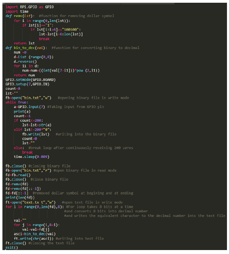
Fig 5: receiver code
- Raspberry pi receives binary sequence from it’s GPIO pin 7.
- It stops taking input from GPIO pin 7 after getting 200 zeros continuously at the same time it puts binary sequence into a file called bin.txt.
- After that it removes the dollar symbol at beginning and at ending by a function called remv().
- Then it takes continuous 8 bit sequences and converts these binary sequences to decimal numbers and writes its equivalent characters into a file called text.txt(text.txt file is also called Base 64 file).
- From this Base 64 file it reconstructs the original file.
Limitations :
In this project there are few limitations which are mainly due components used :
- Low sensitivity of the receiver : Due to low receiver sensitivity, flickering rate of LED bulb should be reduced in order to send the data accurately and this leads to low data rate.
- Interference due to external light : This problem occurs because of the OOK modulation technique and low flickering rate of the LED.
- Due to above limitations the maximum distance between the transmitter and the receiver in the absence of external light source is 100cm and in presence of external light the distance is about 10cm, these distances can be increased by keeping both transmitter and receiver in the line of sight and shielding the receiver around as in a torch light.
- And due to the same reasons the current data rate is low i.e 100bits/s only.
- Synchronization between receiver and transmitter is very important, and it is done using trial and error methods(it is a tiresome process).
Future improvements :
- The limitations mentioned above can be avoided by selecting appropriate and accurate components. As per our research an IC called TSL235R can be used to improve the data rate and distance between the transmitter and the receiver. This IC is basically a light to frequency converter, higher is the intensity of the light falling on it, higher is the output frequency(1 - 10kHz).
- And currently the process of selecting a file from the PC and selecting an appropriate code(for file conversion to base64 and vice versa) to run is being done manually, this problem can be avoided by designing a web app(using Django) where we can automate this process by just a few clicks.
LiFi is the technology of the future and a lot of research is still going on in this field and this is our
small attempt to demonstrate how VLC works. Even though this project has few limitations we
continue to explore new ways to improve its efficiency and immediately update you upon this project.
Hope you enjoyed reading the blog!!
small attempt to demonstrate how VLC works. Even though this project has few limitations we
continue to explore new ways to improve its efficiency and immediately update you upon this project.
Hope you enjoyed reading the blog!!
Have a nice day!! :)


Comments
Post a Comment