Spatial modulation by group 1 - P. Sruti,G. Soumya, T. Bhavani, V.Rishitha, S. Indiramma
Motivation:
Multiple antennas in wireless systems offer a practical way to extend next generation communication capabilities which include higher data rate, reliability and high spectral efficiency.The increase in demand for higher data rates has led to the development of majorly two kinds of MIMO techniques Spatial Multiplexing and Space Time Block Coding (STBC).Spatial Multiplexing using V-BLAST systems are prone to high levels of inter-channel interference as all the antennas can transmit their data streams at the same instant. So, this technique needs complex decoders at the receiver antennas.
On the other hand, Space–time block coding is a technique in which multiple transmitters transmit multiple copies of a data stream to exploit the various received versions of the data to improve the reliability of data transfer and reduce the decoding complexity.
Spatial modulation is another technique which can increase the spectral efficiency. In this technique unlike other MIMO techniques only one antenna remains active at one instant of time. The ground principle of spatial modulation is it maps a block of data to two units -a unique antenna number assigned to each antenna and a symbol chosen from the constellation diagram of the modulation technique used. The location of activated antennas in the domain is used for transmission of data, thus both data and spectral efficiency increase.
Using spacetime block coding with Spatial modulation(STBC-SM) is a very promising technique for the next generation wireless communication.
Simulation Models:
1) Space time block Coding (STBC):
In space time block coding ,multiple copies of a data stream are transmitted across number of antennas. STBC combines all the copies in an optimal which increases the data reliability. This technique helps us to counteract the channel problems like fading and thermal noise that effects the signal.
In general, STBC is represented using a matrix where each row corresponds to the time block and the column corresponds to an antenna.
Here we use Alamouti's STBC which transmits one symbol per channel use because it gives better spectral efficiency and simplified ML detection.We take two information symbols from the BPSK constellation and transmit them from two transmit antennas in an orthogonal form in the following manner.
in the matrix columns corresponds to transmit antennas and rows correspond to time instants.
In the first instant the received signal is y 1 = h1 S1 + h2 S2 + n1
In the second instant received signal is y 2 = −h1 S2* + h2 S1* + n2
Q(k)is an 𝑚 × 𝑛 binary matrix to be transmitted, where 𝑚
= log2(𝑀𝑜𝑑) is the number of bits/symbol and n is the total number of sub
channels. The SM maps this matrix into another matrix 𝐗(k)
of size 𝑁
× 𝑛,
𝑁
is the number of transmit antennas. The matrix 𝐗(k) has one
nonzero element in each column at the position of the transmit antenna number.
The received
matrix is given by:𝒀(𝑡) = 𝑯(𝑡) ⊗ X(𝑡) + 𝑵(𝑡)
SM Mapping
Table (3 bits per symbol)
Input Bits
(3-bits)
|
N = 2, Mod = 4
|
|
Antenna Number
|
Transmit Symbol
|
|
000
001
010
011
100
101
110
111
|
1
1
2
2
3
3
4
4
|
-1
+1
-1
+1
-1
+1
-1
+1
|
3) STBC – SM:
Now we combine the above two by
making it STBC-SM system. Here the transmitted data depends on space time and unique
antenna indices.By using this system, we get optimised diversity and minimum error
(with the usage of space and time domains) The system is designed for four transmit antennas and depends on
Almouti(STBC) in forming the following transmitter matrices. Every two code
words is a one STBC-SM codebook X1 , X2.The spectral efficiency becomes, m = 1 + log2(Mod) bit/s/Hz. 𝜃 is a rotation angle to be optimized for a given modulation scheme to ensure maximum diversity and coding gain at the expense of expansion of the signal constellation.
Transmitter:
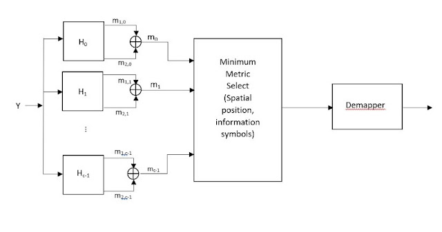
Receiver:
Algorithm used to design the STBC-SM scheme:
- Calculate the number of possible antenna combinations for transmission of Almouti’s STBC by determining the total number of transmitter antennas.
- The number of code words in each codebook.
- Construction of the Xi for 2<= i <=n which contains a non-interfering code words by considering the following facts:
- Each codebook must be composed of code words with antenna combinations that were never used in the construction of a previous codebook.
- Every code-book must contain non-interfering code words chosen from pairwise combinations of available transmitter antennas.
STBC-SM is compared to other schemes like SM other in terms of their bit error rate with respect to code length.


Comments
Post a Comment